

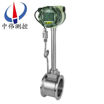
High pressure type vortex flowmeter
High pressure type vortex flowmeter has the LCD meter, according to the real-time temperature, real …
Description:
Products overview:
ZW - LUGB seriesHigh pressure type vortex flowmeterMainly refers to the vortex flow sensor can withstand high pressure, to withstand high pressure, from the material of vortex flow sensor, vortex flow sensor parts on the structure and vortex flow sensor assembly are taken very strict measures.Vortex flowmeter is divided into low pressure, medium pressure and high pressure type, when the medium pressure to 10 mpa P 42 mpa, or less or less high pressure vortex street should be adopted.High pressure vortex street can be divided into flange mounted and welded, contrast, welded more safe and reliable.Using piezoelectric stress sensor, high reliability, can be in - 20 ℃ ~ + 350 ℃ temperature range.There are standard signal simulation and digital pulse signal output, easy with the computer and digital systems, is a more advanced, the ideal measuring instrument.
Second, the working principle:
ZW - LUGB seriesType high pressure principle of vortex flowmeter is by the design, testing probe in the flow field in the vortex body and the corresponding electronic circuit, etc.When the fluid flows through the spiral body occurs, it is formed on both sides of the two rows of vortex variations, this vortex is known as the karman vortex street.On the basis of the theory of karman vortex street and proposed the karman vortex street frequency is proportional to the velocity of the fluid, the relation between the frequency and velocity are presented: f = St * V/d type:
F vortex frequency (Hz)
V vortex occurred body on both sides of the average flow velocity (m/s)
St, luo hall coefficient (constant)
These variations of vortex is formed a series of variations of negative pressure, the pressure on detecting probe, and produce a series of alternating electric signals, after dealing with the preamplifier conversion, plastic, amplification, the output is proportional to the vortex synchronous pulse frequency signal (or standard).
Applications:
ZW - LUGB seriesHigh pressure type vortex flowmeter can be widely used in large, medium and small various water supply and drainage pipe, industrial circulation, sewage treatment, oil and chemical reagents and compressed air, saturation and superheated steam, gas and all kinds of medium flow rate measurement.
Four, the main features:
1, simple structure and strong, have no moving parts, high reliability, long running is very reliable.
2, installation is simple, maintenance is very convenient.
3, detection sensor is not direct contact with the measured medium, stable performance and long service life.
4, the output is the pulse signal is proportional to the flow, no zero drift, high precision.
5, wide measuring range, range than can reach 1:10.
6, small pressure loss, low operation cost, more energy saving.
7, in a certain range of Reynolds number, the output signal frequency is not affected by changes in the fluid physical properties, and components, instrument coefficient only involved in the body shape and size of the vortex, fluid volume flow measurement without compensation, generally need to calibration instrument coefficient after changing accessories.
8, wide application range, steam, liquid, gas flow rate can be measured.
Five, the technical parameters:
1, the nominal diameter: DN25mm ~ DN200mm;
2, scope of application: gas: : air, carbon dioxide, oxygen, nitrogen, gas, natural gas, methane and other various chemicals, etc.;
Liquid: water, high temperature water, oil, food, liquid, chemical liquid, etc.;
Steam: saturated steam and superheated steam;
3, measurable medium temperature: explosion-proof medium: - 40 ℃ ~ 100 ℃;Low temperature medium: - 40 ℃ ~ 100 ℃;
Medium temperature medium: - 40 ℃ ~ 280 ℃;High temperature medium: - 40 ℃ ~ 350 ℃;
4 nominal pressure, low pressure: 1.6 MPa, l2.5 MPa;Mp: l4MPa, l6.3 MPa;
High pressure: l11MPa, l15MPa, l26MPa, l42MPa;
5, precision grade, measurement of liquid: grade 1 (0.5 magnitude order agreement);
Measuring gas: 1.5 on the Richter scale (grade 1 to order agreement);
Measurement of steam: 1.5 on the Richter scale (grade 1 to order agreement);
6, velocity range: liquid: 0.3 ~ 8 m/s, gas: 3 ~ 65 m/s, steam: 3 ~ 70 m/s;
7, output signal voltage pulse: low level l1V, high level g6V;
8, the standard current: 4 ~ 20 ma;
9, the power supply voltage pulse output: + 12 VDC / + 24 VDC;4 ~ 20 ma;
10, the standard current output: + 24 VDC;
11, the liquid crystal display: 1 1 section 3.6 V lithium battery power supply, service life is more than 2 years;
12, the environment temperature: - 30 ℃ ~ + 55 ℃;
13, table body material: 304, other materials can be supply agreement;
14, protection grade: IP65, IP67;
15, explosion-proof grade: Exia Ⅱ CT4.
Six, appearance size:
DN | A | B | C | D |
15 | 90 | Φ 57 | 383 | 45 |
20 | 100 | Φ 57 | 388 | 50 |
25 | 100 | Φ 57 | 394 | 50 |
32 | 100 | Φ 65 | 396 | 50 |
40 | 100 | Φ 75 | 401 | 50 |
50 | 110 | Φ 87 | 407 | 55 |
65 | 110 | Φ 109 | 418 | 55 |
80 | 110 | Φ 120 | 423 | 55 |
100 | 120 | Φ 149 | 447 | 60 |
125 | 125 | Φ 175 | 474 | 65 |
150 | 145 | Φ 203 | 501 | 75 |
200 | 170 | Φ 259 | 556 | 100 |
250 | 190 | Φ 312 | 608 | 120 |
300 | 210 | Φ 363 | 660 | 140 |
350 | 230 | Φ 409 | 709 | 160 |
400 | 250 | Φ 460 | 756 | 180 |
450 | 275 | Φ 520 | 814 | 205 |
500 | 290 | Φ 575 | 869 | 225 |
Seven, requirement for straight pipe:
In order to ensure that the instrument, accurate to run normally, sensor must have a certain straight pipe upstream and downstream of the installation points, to adjust the flow field, as shown.
Figure 1: concentric contraction tube;
Figure 2: the concentric expansion tube;
Figure 3: a 90 - degree Angle;
Figure 4: the same plane of two 90 - degree Angle;
Figure 5: different plane of two 90 - degree Angle;
Figure 6: regulating valve should be installed downstream of the sensor in 5 d to the distance, if the sensor must be installed in the upstream, the sensors should be not less than 50 d upstream, straight pipe section downstream straight pipe section should be not less than 5 d.
Eight, the requirement of pipe:
1, upstream and downstream piping diameter D, and the same as the sensor inner diameter DN, its difference satisfy the following conditions: 0.95 DN D 1.1 or less or less DN.
In 2, piping should be one of the sensor, the coaxial degree should be less than 0.05 DN.
3, gasket not protruding into the pipe, the inner diameter slightly larger than sensors.
4, if you want to stop inspection and cleaning the sensor, the by-pass pipe should be set up, as shown in the figure below.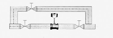
Nine, the requirement of pipe vibration:
Sensors to avoid installed on the strong pipeline vibration, if necessary to install, shock absorption measures must be taken, respectively at the upstream and downstream of sensor 2 d piping fastening device, and vibration-proof pad.
Special note: in the air compressor exit strong vibration, cannot install the sensors, shall be installed after the gas storage.
Ten, installation requirements:
1, the sensor can be installed indoors, can also be installed in the outdoor.Environmental conditions to conform to the requirements.
2, sensors should be installed in a horizontal, vertical or inclined (fluid flow from bottom to top) and its corresponding pipe nominal diameter.
3, sensors installed on a mechanical vibration of pipeline should be avoided.Should be considered when the vibration is inevitable, at about 2 dn from sensor before and after the straight pipe and fixing racks.
4, avoid install the sensor sensing has strong electromagnetic interference, thermal radiation, corrosive gas, the space is little, and maintenance is not convenient.
5, when measured medium contains many impurities, at the request of straight pipe upstream from sensors mounted outside the length of the filter.
6, either upstream or downstream of the sensor should be configured with a certain length of straight pipe, straight pipe inner surface should be clean, smooth, no obvious convex concave, fouling and peeling phenomenon.Its length should conform to the requirements of figure 2.Installation of the liquid sensor, near the pipe should be filled with liquid to be tested.
7, straight pipe diameter as far as possible consistent with the sensor size, if not consistent, slightly larger diameter than the sensor size should be adopted, the error to 3% or less is not more than 5 mm.
Eleven, notable matters of installation:
1, special flange and straight pipe welding can't with the sensor.
2, when installation should make the flow of sensor mark the direction of flow and the pipe.
3, before the installation of sensor and the flange must be put away in sealing ring grooves.The location of the pressure and temperature measurement point, pressure downstream of the sensor in 3 ~ 5 dn, temperature measuring points in the downstream of 5 ~ 8 dn.
4, when measuring high temperature medium, do not use heat insulation material to wrap around the sensor link rod.
Five, connection of shielded cable, should as far as possible away from the interference of strong electromagnetic field.Absolutely not allowed with high voltage cable laying, shielded cable to shorten as far as possible, and shall not be volume, in order to reduce stray inductance, z great length should not exceed 200 m.
6, before installation of sensors, pipeline cleaning must be conducted.Flow after rinse tube impurities, avoid clogging sensor.Measuring liquid pipe must be full of measured liquid, prevent the interference of bubbles.
7, measuring gas pipelines to prevent the interference of reservoir fluid.Installation position as shown in figure 5.Replace the probe body under the high temperature and high pressure, it must be safe operation, high temperature protection.After cooling step-down replaceable probe at the bottom of the safety conditions.
Twelve, selection of points:
1, as far as possible not to use in the selection of flowmeter work flow in the lower limit value, so the meter diameter should be as small as possible, in order to obtain larger flow velocity and flow range.
2, the flowmeter should be used in the technical parameters of medium pressure and temperature range.Don't deliberately choose the high pressure level and ultra-high temperature instrument, should be selected according to the actual work pressure and temperature instruments, which had higher prices.
3, in the explosive dangerous location, should choose explosion-proof type flowmeter.
4, the lower limit of vortex street flowmeter flow depends on the operation condition of the medium density and kinematic viscosity, the maximum flow is generally not affected by medium pressure and temperature, so to determine the flow range as long as you determine the actual minimum flow can be available.Calculate the minimum flow rate, flow range check table to determine the appropriate diameter.
13, standard of flow range profile: unit (m3/h)
traffic | The liquid flow range | Gas flow range | Saturated steam flow range | |||
CAL | Small flow | Heavy traffic | Small flow | Heavy traffic | Small flow | Heavy traffic |
DN25 | 0.9 | 14 | 8.3 | 110 | 13 | 1500 |
DN40 | 2.5 | 35 | 26 | 300 | 25 | 4400 |
DN50 | 3.3 | 55 | 36 | 480 | 40 | 6800 |
DN80 | 8 | 150 | 90 | 1300 | 100 | 19000 |
DN100 | 14 | 240 | 140 | 2000 | 160 | 29000 |
DN150 | 38 | 450 | 290 | 4100 | 350 | 66000 |
DN200 | 70 | 850 | 620 | 7500 | 620 | 118000 |
DN250 | 130 | 1300 | 700 | 12500 | 970 | 185000 |
DN300 | 180 | 2000 | 920 | 16500 | 1400 | 267000 |
14, selection of coding:
Code name | size | Flow range ㎡/h(In the wei and control) | ||||
ZW-LUGB-25 | DN25 | 1 ~ 10(liquid) | 25 ~ 60(gas) | Steam flow check specifications,DN300The above recommended plug-in vortex flowmeter | ||
ZW-LUGB-32 | DN32 | 1.5 ~ 18(liquid) | 15-150(gas) | |||
ZW-LUGB-40 | DN40 | 2.2 ~ 27(liquid) | 22.6 ~ 150(gas) | |||
ZW-LUGB-50 | DN50 | 4 ~ 55(liquid) | 35 ~ 350(gas) | |||
ZW-LUGB-80 | DN80 | 9 ~ 135(liquid) | 90 ~ 900(gas) | |||
ZW-LUGB-100 | DN100 | 14 ~ 200(liquid) | 140 ~ 1400(gas) | |||
ZW-LUGB-150 | DN150 | 32 ~ 480(liquid) | 300 ~ 3000(gas) | |||
ZW-LUGB-200 | DN200 | 56-800(liquid) | 550 ~ 5500(gas) | |||
Code name | function1 | |||||
N | No temperature pressure compensation | |||||
Y | With temperature compensation | |||||
Code name | Output type | |||||
F1 | 4-20mAOutput (two-wire system) | |||||
F2 | 4-20mAOutput (three-wire system) | |||||
F3 | RS485Communication interface | |||||
Code name | Measured medium | |||||
J1 | liquid | |||||
J2 | gas | |||||
J3 | steam | |||||
Code name | The connection method | |||||
L1 | Flange mounted | |||||
L2 | Flange connection type | |||||
Code name | function2 | |||||
E1 | 1.0level | |||||
E2 | 1.5level | |||||
T1 | The normal temperature | |||||
T2 | The high temperature | |||||
T3 | steam | |||||
P1 | 1.6MPa | |||||
P2 | 2.5MPa | |||||
P3 | 4.0MPa | |||||
W1 | internal3.6VThe power supply | |||||
W2 | DC24VThe power supply | |||||
N1 | Stainless steel | |||||
N2 | Carbon steel | |||||
N3 | Anti-corrosion type | |||||
15,Order to choose selection guidelines:
Name and model number of 1, 1), (2) the diameter, flow range, (3) whether or not to bring the attached so that we can correct selection for you, (4) using pressure, (5) the use of medium temperature.
2, if has been selected by design units in the way of vortex street flowmeter types, please press type vortex flowmeter directly order from our sales department.
3, when using occasions is very important, or the environment is complex, please try to provide the design drawings and detailed parameters, by wei experts in our audit checks for you.
After-sales service commitment:
1, from the date of signing of the contract, I in the way provided for products of the company offers free maintenance and maintenance service, commitment to lifelong maintenance service;
2, jiangsu wei measurement and control instrument co., LTD. Sales manager will be in regular contact with customers, understand the usage of products, and solve the problems of the customers to use in the process of produce, free of charge to provide technical support;
3 the man-made damage is found, the warranty period, our company is responsible for the maintenance, and the resulting maintenance fee;
4, product quality problems or are not satisfied with product, the user can choose unconditional return, wei tt&c don't charge any fees, appear quality problem, bear the freight back and forth.
Browse:
